How multi-wire sawing turns a silicon ingot into wafers
A multi-wire saw does not cut with a blade. It uses a single, very long wire wound hundreds of times around grooved rollers, forming a dense web of parallel wire segments. Pushed through that web, a silicon block is cut into hundreds of wafers in one pass.
From crystal to wafer
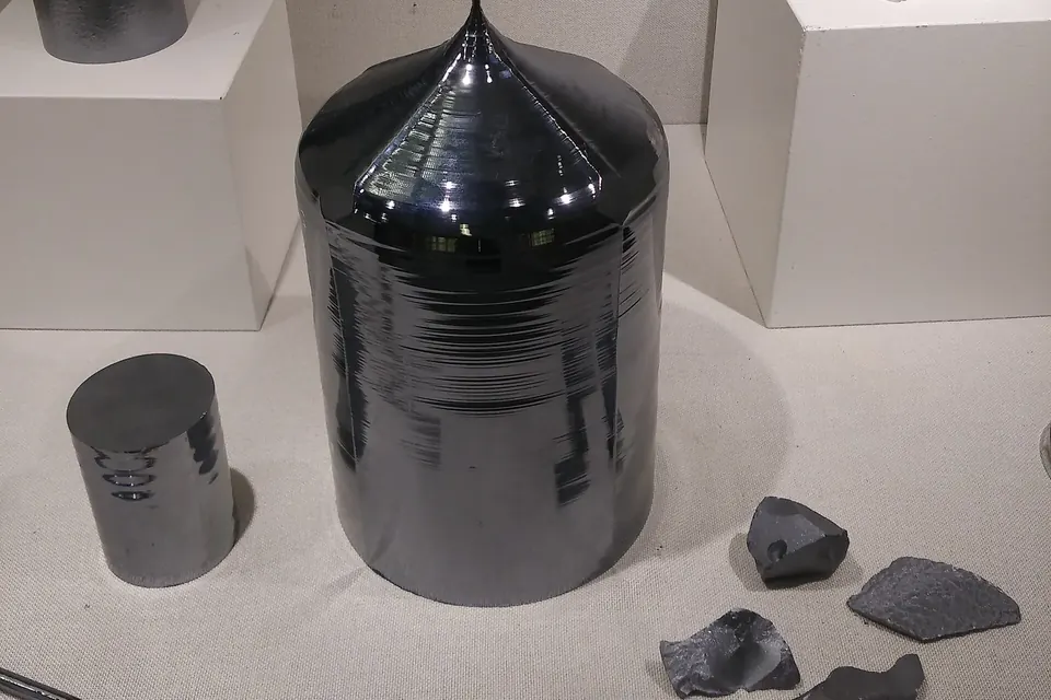
Wafering starts with a crystal: either a pulled single crystal (monocrystalline) or a cast block (multicrystalline). The open teaching platform PV Manufacturing, run by the University of New South Wales (UNSW), describes the steps for a solar-grade single crystal: grinding the ingot to the target diameter, cutting off four side slabs to obtain a "pseudo-square" brick, gluing the brick onto a glass plate, and finally sawing it in the wire web (PV Manufacturing, "Wafering").
Either the brick is fed slowly into the fast-moving wire web or the web is lowered onto the brick. Because every wire segment cuts at the same time, one pass yields as many wafers as there are segments in the web. The spacing between two segments sets the wafer thickness plus the kerf.
Anatomy of a multi-wire saw
Wire web and wire guides
The heart of the machine is a set of two or more wire guide rollers with precisely machined grooves. The wire runs from a supply spool over the rollers, wraps once around each groove and is wound onto a take-up spool at the end. The groove pitch fixes the distance between wire segments and therefore the final wafer thickness. A tensioning system keeps the wire under a defined load: a slack wire vibrates sideways and widens the cut.
Drive and wire motion
The wire can run in one direction or reciprocate. In reciprocating mode, each cycle moves slightly more wire forward than back, so fresh wire keeps entering the cut. For the slurry process, the UNSW source gives wire speeds of about 10 m/s and a brick feed rate of less than 1 mm/s; a typical brick took six to eight hours to cut.
Abrasive or coolant supply
Nozzles or curtains feed the wire web with either a slurry of loose abrasive or a coolant, depending on the process. The liquid carries grit into the cut, removes heat and flushes the removed silicon out of the kerf.
Two cutting principles: loose and fixed abrasive
| Feature | Slurry sawing (loose abrasive) | Diamond wire sawing (fixed abrasive) |
|---|---|---|
| Cutting agent | Silicon carbide grains dispersed in a carrier fluid | Diamond grains bonded to the wire |
| Wire | Plain or structured steel wire that carries the grit | Steel core wire with a diamond coating |
| Liquid | Usually polyethylene glycol (PEG), see slurry composition | Mostly water-based coolant with a few per cent additives |
| Removal mechanism | Rolling, indenting grains (three-body abrasion) | Scratching, fixed grains (two-body abrasion) |
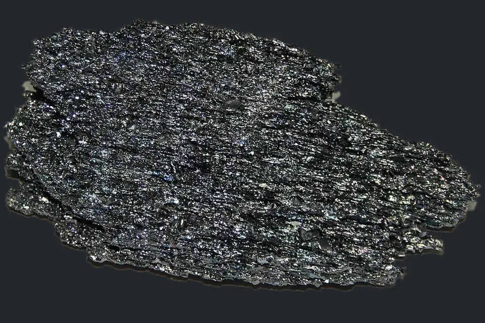
In slurry sawing the wire itself does not cut. It drags grains into the gap between wire and silicon, where they roll, indent the brittle surface and chip out small fragments through micro-cracks. This "rolling-indenting" model, comparable to fast lapping, is widely used in the literature; a review by Gopala Krishna Murthy summarises the proposed mechanisms and what they mean for the condition of the spent slurry (Resources, Conservation & Recycling 104, 2015).
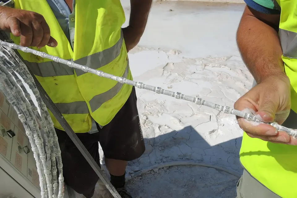
With diamond wire, the grains sit firmly in the coating and scratch the silicon. That allows thinner wires and higher speeds but changes the wafer surface; see the switch to diamond wire.
Kerf, wafer thickness and yield
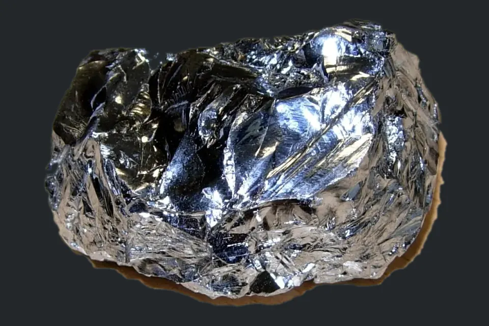
Each wire segment leaves a kerf wider than the wire, because grit sits on both sides and the wire vibrates. For classic slurry sawing, the UNSW source cites a 180 µm steel wire and a kerf loss of about 200 µm per cut. When the wafer itself is of the same order of thickness, a large fraction of the crystal is turned into powder. That fraction ends up in the sawing sludge, which is why recovering silicon from kerf has been studied for years.
Saw productivity can therefore be described with two numbers: how many wafers are obtained per millimetre of brick (set by wafer thickness plus kerf) and how many of them pass inspection.
Quality criteria of as-cut wafers
- Total thickness variation (TTV): the difference between the thickest and thinnest point of a wafer, caused among other things by grit wear along the cut and by temperature gradients.
- Saw marks: visible grooves caused by wire breakage, grit starvation in the gap or changes in the slurry. A multi-wire saw patent explicitly names slurry viscosity changes as a cause of thickness variation and saw marks (US 7,306,508 B2).
- Sub-surface damage: a micro-cracked layer under the surface that is etched off before cell processing. According to the UNSW source it is roughly half as deep on diamond-sawn wafers as on slurry-sawn ones.
- Fracture strength: micro-cracks and saw marks largely determine how easily a thin wafer breaks during handling.
Why heat matters
Friction in the kerf generates heat, which can expand the brick, the rollers and the wire unevenly. A patent on temperature control therefore describes actively cooling the slurry before it reaches the wire web, so that it removes heat as it passes through the cut and reduces thickness variation and warp (US 7,878,883). In practice, temperature and flow of the supplied liquid are tightly controlled.
After the cut
Once sawn, the wafers still hang from the glass plate like the teeth of a comb. They are pre-cleaned, released from the adhesive, singulated, cleaned and inspected. The used liquid, with grit, silicon fines and wire debris, leaves the saw as sludge. What it contains, and why it is worth treating, is the subject of why sawing slurry is recycled.
 Sawing & Wafers
The switch to diamond wire
Fixed abrasive, thinner wire, water instead of glycol, and what that meant for wafer surfaces and recycling.
 Slurry & Recovery
What a sawing slurry is made of
SiC grit, polyethylene glycol and additives: what each component does and how the slurry wears out.
 Slurry & Recovery
Kerf loss and silicon recovery
How much silicon is lost in the cut, why it is hard to win back and which recovery routes research describes.